Bass boost active and passive collection of circuits for all
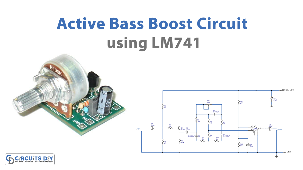
While supplying the power to this Active Bass Boost circuit using IC 741, we input an audio signal through a coupling capacitor C1, is. The signal then goes via R3 to the base of Q1. Thus R1 and R2 work together as a voltage divider to control Q1's bias current. As part of a typical preamplifier circuit, Q1, C1, R1, R2, R3, R4, and C2 are.
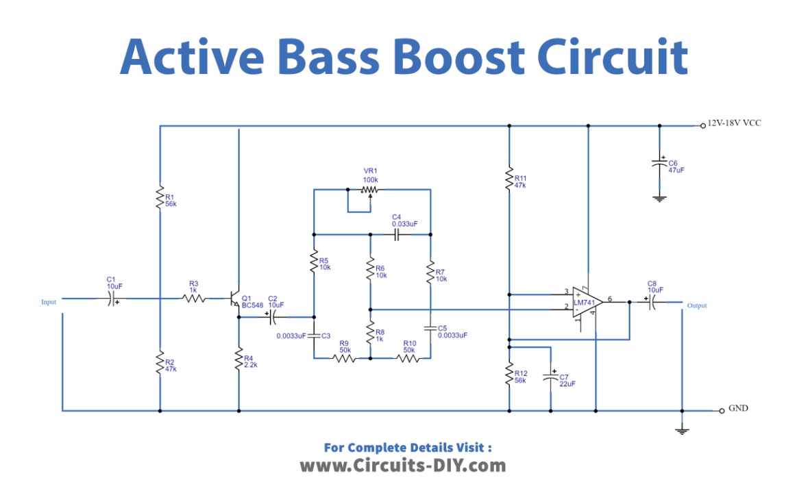
Active Bass Boost Circuit using LM741
Passive bass tone control circuits work by selectively attenuating or boosting certain frequencies in the audio signal. This is typically done using RC networks, which are composed of a resistor and capacitor in series or parallel.
lm324 amplifier circuit diagram Wiring Diagram and Schematics
In this video, we are going to show you making an audio base booster circuit easily. You can make this circuit at home easily. It is a very simple tricks of digital electronics. You can.
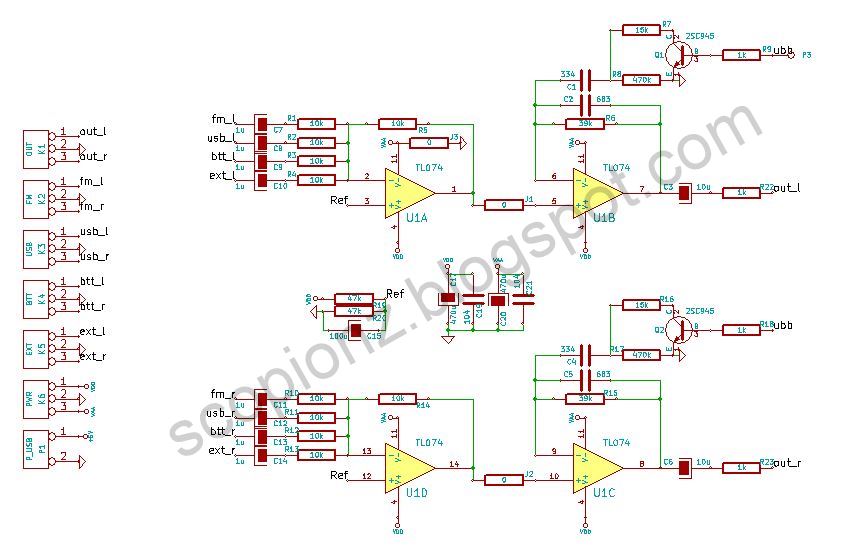
Stereo Bass Booster Amplifier Electronic Circuit
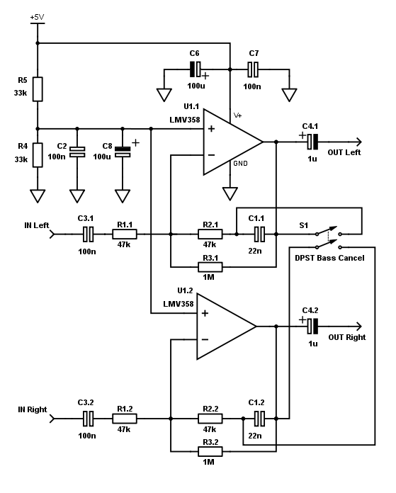
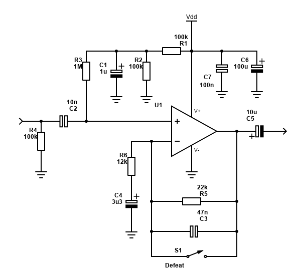
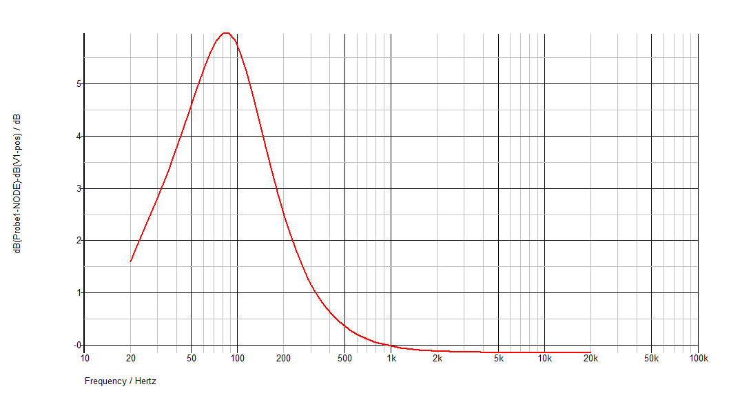
This circuit features also a bass-boost, in order to overcome this problem. You can use a variable resistor to set the bass-boost from 0 to a maximum of +16dB @ 30Hz. If a fixed, maximum boost value is needed, the variable resistor can be omitted and substituted by a switch. Notes:

Boost Bass boost circuit addition Chelsea Guitars Reverb
A low pass filter circuit Bass Booster is an essential component in audio systems that enhances the bass frequencies of an audio signal. The JRC4558 IC, an integrated circuit, is widely used in low pass filter circuits due to its superior performance and versatility. This circuit is known for its ability to isolate low-frequency sounds and.
Transistor Stereo Bass Booster Circuit C1815
Step 1: Bass Booster Circuit Connection First We Connect Mylar Polyester Film Capacitor With Left Leg Of Potentiometer. Then Connect Another Mylar Polyester Film Capacitor With Right Leg Of Potentiometer & Connect The Empty Leg Of Mylar Polyester Film Capacitor.

Layout Pcb Bass Booster PCB Circuits
Block Diagram - Fig. 2: Block Diagram of Bass Boost Amplifier Circuit Connections - This amplifier circuit is built by assembling the following components together - 1) DC Source - A battery of 12V rating is used to power the circuit.
Active Bass Boost Circuit using LM741
For 6 dB effective bass boost: R . 15 kΩ, the lowest value for good stable operation is R = 10 kΩ if pin 8 is open. But I do not understand how it works, as far as I knew the bigger the cap the less capacitive resistance it has, so wouldn't a small cap (0.033 µf) as in the diagram be more resistive to bass frequencies?
Bass boost Battery operated opamp circuit
What does basic work? It is a low pass filter circuit that looks like a bass function on the tone control. But it works well than that. Sound good, is it? Let's get started. Table of Contents hide How Active Bass Booster circuit works Bass booster Connection How to build Caution The parts you will need Related Posts

GXA604 4 channels, fullrange amplifier with electronic filter and variable Bass EQ on the
Bass boost circuit: This is the Bass boost circuit diagram for the amplifier. this circuit runs with 12 voltages. it's a mono pre-amplifier diagram. Bass boost, bass, and table are in this diagram. if we need stereo sound then we have to use 2 circuits. P1=100n.
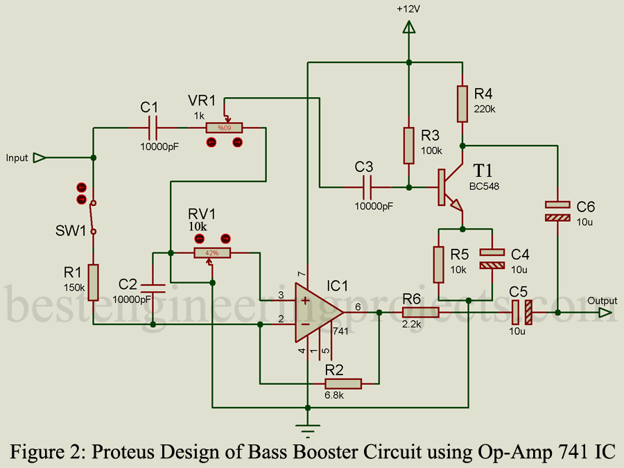
Bass Booster Circuit using OpAmp 741 IC Engineering Projects
RIAA phono pre amp RIAA phono amps are in fact BASS BOOST circuits If you skip the highest lowpass filter (2122 Hz), you get a bass boost filter that boost low frequencies. It will boost most below 50 Hz and get flat at about 500 Hz So you only have to modify a RIAA feedback filter in an OPamp. And select to wanted gain, of course.
Simple Bass Treble Tone Control Circuit
Step 1: LM386 BASICS In this tutorial, I'll show you how to build a great sounding audio amplifier with the LM386 Low Voltage Audio Power Amplifier. I built about a dozen different audio amplifier circuits with the LM386 but most of them had way too much noise, popping, and other interference.
ฅนบ้ายอ [28+] Circuit Diagram Of Booster Amplifier
The bass boost will amplify the troublesome rumble frequencies (below 20 Hz), causing distortion and dynamic range to suffer. So really these circuits are more suited to improving sound quality when you're listening to music in a hotel room (quietly!), improving the sound of many TV or radio speakers, rather than partying with friends.

electronics4u Bass boost circuit for audio amp
A bass boost serves as an electronic circuit that improves low-frequency sounds through an amplification circuit. These generally integrate into consumer electronics to enhance sound quality. 2. How to Make Bass Boost Circuits We introduce three different bass boost projects: Using 2n2222 transistor Circuit diagram:
Bass Booster Circuit design
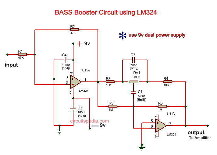
Bass booster circuit diagram. This bass booster circuit is made using the quad op-amp ic LM324. This op-amp ic has 4 operational amplifiers, but in this circuit, only 2 op-amps are used. This circuit provides Low pass filter of input audio which produces a Low frequency of input and high frequency is blocked.
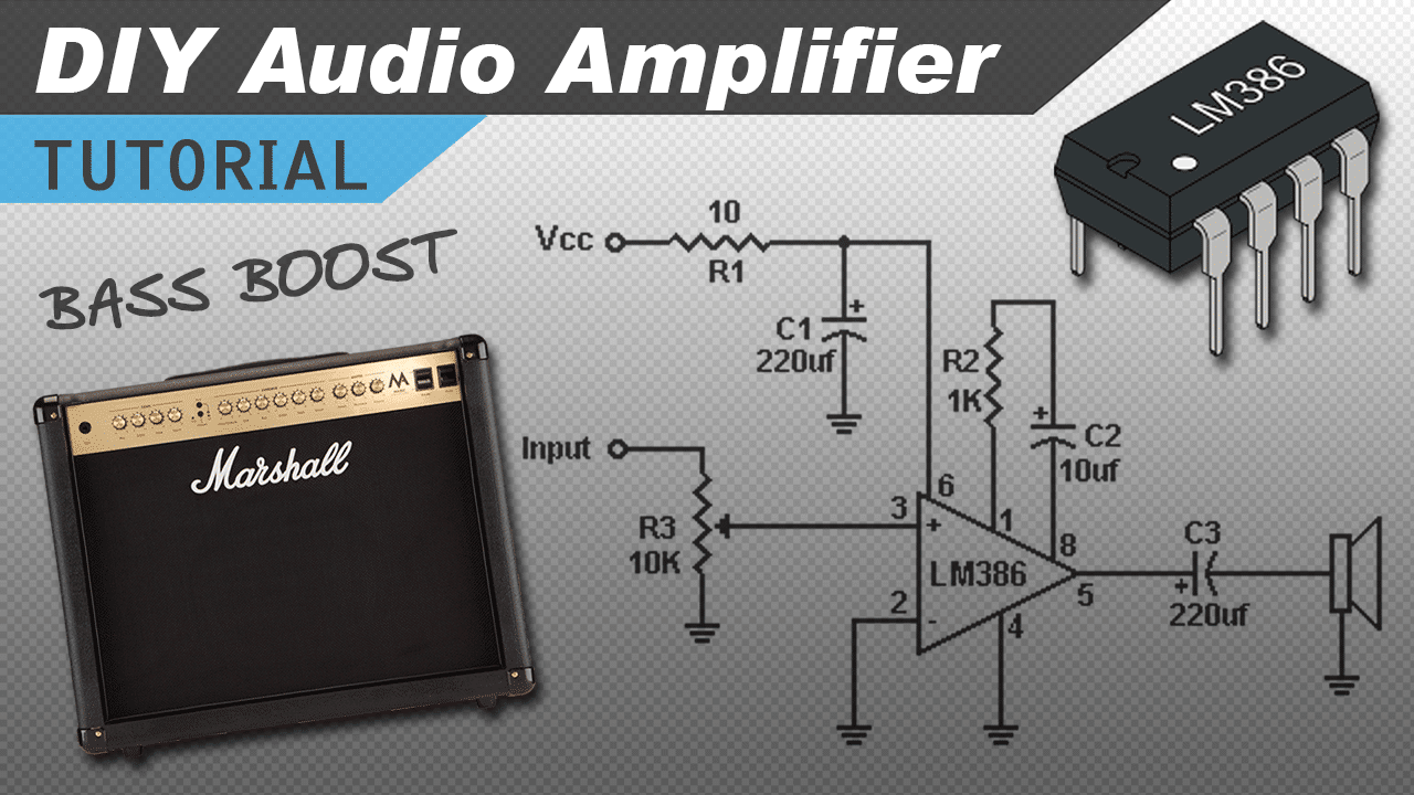
[VIDEO] Make a Great Sounding LM386 Audio Amplifier with Bass Boost Circuit Basics
An Electronic Bass booster is an electronic circuit that operates in conjunction with an amplifier circuit, improving its output response. It is commonly fitted in basic consumer electronics such as speakers, gaming headsets & earbuds to improve the listening experience. Hardware Components